I can't be the only one to find myself lost in the internet rabbit holes in an age such as ours. Sometimes it's an uninspiring frustration, and other times you find yourself on the path to discovering something truly cool. A few weeks ago, I stumbled upon a group of unique creators making what they called "cyberdecks." The concept was a dystopian-esque or retro-futuristic portable computer, in part inspired by the cyberpunk movement, Blade Runner, and Fallout, though there are plenty of other sci-fi extravaganzas that employ similar devices. The cool thing about cyberdecks is that they work, and there is no right way to create one. There come in a variety of shapes and sizes, some in the traditional clamshell style, and others that their own entirely new concept.
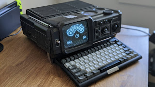
I had toyed around with the idea of creating a small portable computer, and decided I would give it a shot. I've always been a fan of the aesthetic of old computers, so I decided to try and build one into a CRT display. My original idea was to use a Sony Watchman, but it ended up being far to small to do anything useful with. The unit I eventually found was a Magnavox portable television/radio. I figured it would look pretty cool as a computer.
A CRT IS A HIGH VOLTAGE DEVICE, HANDLED CARELESSLY IT CAN SERIOUSLY INJURE OR KILL YOU. SO CONSIDER YOURSELF WARNED, TREAD LIGHTLY, AND KNOW THAT IT IS NOT MY RESPONSIBILITY IF YOU GET HURT.
first impressions
I picked the unit up off of eBay for a pretty low price, but was assured that the screen powered on. Since the cancellation of analog broadcasting in the US, all VHF and UHF televisions are completely useless. These units need to be hardwire modified to accept a composite video signal. The other thing to search for was a single board computer module. I chose the Raspberry Pi 4, a widely available unit that outputs a composite video signal and runs off of relatively low voltage. There were a few downsides to using one of those, but I'll get to those later.
The core design was simple, I didn't intend to modify the casing much, and wanted the radio to continue to work. I decided I wanted mouse and keyboard to come out the front to replace the TV band tuner, and a keyboard matching in size sitting in front like the Commodore SX-64. I saw some similar designs based around the Sears branded portable TVs after I purchased this unit, and I found those to be very cool, though I did enjoy the boxier look on mine. Maybe another project another time.
a similar concept by r/drake9800 on Reddit using a Sears/Sanyo
As soon as I got the TV, I removed the five case screws and separated the radio unit and top lid. The construction was rather simple, I unplugged the control, power, and audio to the radio and cut the antennae cable out. Then I noticed that the power board was shattered into multiple pieces, the TV did not power on like I was told it would.


It was also overall more complex than I was anticipating. The Sony units tended to employ IC chips to convert the RF signal into composite, I imagined it would be the same here, but as it turns out the only chips on the board were a couple of 8 pin amps. The two silver boxes on the right were the UHF and VHF tuners, which input a video signal through an IF channel. If you followed that trace across the board, one could theoretically find the point where it turns into composite. The first thing I noticed were seven wires in a line coming off the board and going straight to the video amp board on the back of the tube. Turns out that one of those leads was my video signal. I had also considered removing the tuner units, but I decided to leave them as it didn't really accomplish much other than extra work.


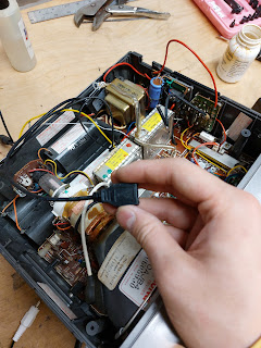
The first thing I had to sort out with the unit was how to get the CRT to power on in the first place. The power board accepted AC, DC, and batteries, but was broken into three or four separate pieces. The AC wires go directly to a transformer which output about 15v, and then into a simple bridge rectifier (four diodes in a square backed up with capacitors) to transform it to DC current. This is then split through a series of components, grounded, and passed through a fuse on the other half of the board. It took a bit of time to figure out which traces needed to be bridged with spare wire before I could get the unit to power on.
One bridge from the DC input to who knows where
the bridge rectifier
The second larger bridge
and power to the tube!
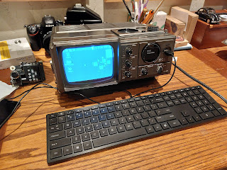
I placed a mirror in front of where I was working so I could both access the board and see the screen. Once I had power to the tube, I was able to extend the ground wires to a common ground point and begin probing the bottom of the board. Rather than use an Oscilloscope, I decided to use a VHS camcorder. I cut an RCA lead, grounded it to the TV, and used the end of the signal wire to locate the video path. All in all, it was a lot easier than I thought. The audio was grounded to the same point, and soldered into the board. It worked, but sounded terrible. That circuit was more complex strangely enough, but since I had no intention of using it for a whole lot of audio stuff, I decided to leave it as is.
my poorly placed audio lead
a 12v to 5v step down USB adapter
working video
The next step after video was to install the Raspberry Pi. I downloaded a copy of the basic OS onto an SD card and made sure the program booted. Output to composite had to be configured, as it is generally disabled by default in favor of HDMI cables. I also ended up spending way too much money on wires, half of which were not used in this project.
The Pi draws power through a USBC plug which I wired in through a step down transformer on the main board. Composite came from the headphone jack, and the four USB ports would be used for data transfer, mouse, and keyboard. I used JB weld to attach two L brackets to a USB extension cable and screwed it into the front of the unit. That was the keyboard connection. The mousepad was manufactured by a company called Ergo Touchpads, and this was their smallest model. It was a PS2 only mouse, so I also needed to put a PS2 to USB converter inside. The touchpad was mounted to the viewing window where the UHF and VHF channel selector was originally displayed.
I scratched off the RF labels and taped in one of my own
Filed a slot in the side for the wire
and here it is mounted
Once the keyboard, mouse, and power were installed, I then had to figure out composite output. The cable I ordered ended up not fitting within the confines of the TV case. I assumed there would be enough room inside for everything, but that was not the case. The Pi fit right beside the CRT tube, I bolted a plastic plate to it so nothing would short out, and ended up having to use a right angle headphone jack from a pair of broken earbuds. It didn't take long to figure out which wires went to what, and everything was grounded and soldered. At this point, the unit was basically working.
The backplate
a simple GPIO fan mounted to the board
the mess of cables (it gets worse)
The braided headphone cable, and my attached leads.
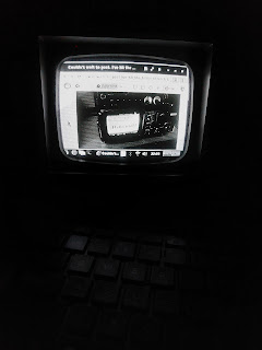
the desktop boots!
It took a little bit to get the desktop to display right. It still hangs off the edge of the display on the right, but I was able to configure it in such a way that the taskbar is evenly cropped and displayed across the bottom. I ran some tests on the unit and all seemed to work well. The only thing I had left to do was to install the USB 3.0 connections, and a separate power switch.
Now for the downsides. The Pi operates off a Linux based system, and an SD card. Both of which are very sensitive to sudden loss of power. They need to be securely shut down from the software side to avoid data corruption. The other downside is slow wifi but whatever. I decided to mount a power switch that would boot the Pi independently of the unit itself, so I could not only control when it shut off, but also use the radio without worrying about data loss. This also meant that the unit could remain plugged in or have batteries installed without the Pi booting up. I cut all the holes and soldered all the wires in the span of a couple hours, though when I ran a battery test, I ended up having to resolder the 5v power supply since it was drawing power from the wrong trace. The battery bay connects to the power board further along than the DC from the bridge rectifier.
testing
the ports
more testing/redditting
home stretch
the wrong power connection, see the red wire far left on the
bottom of three traces
fixed, and insulated with duct tape. Those are the switch leads
Mounted is the switch, facing down, and the keyboard
connector cable screwed in firmly
Two rear mounted USB 3.0 panels, removed the internal
speaker to access them.
All the components together. Had to cut one of the
support posts out to fit the USB wires.
It ended up being a very long project, long but rewarding. It is probably one of the coolest things I've built, or at least it is to me. I do intend to hook up a rechargeable battery pack at some point, that would solder into the battery compartment. I also want to stitch some leather saddle-type bags to hold extra cables and the keyboard, which is a custom built 60% layout with arrow keys.
the portability test on 9 D cell batteries
The keyboard features Gateron Silent Brown switches. I needed something quiet for late typing sessions, and I wanted a nice aluminum case. Turns out the PCB actually bowed and shorted on the back of the case, so I needed to support and insulate that with paper towels and cardboard. Super high tech, I know.
Nothing says pro-keyboarding like paper towels and cardboard
And that was the last step. I may work further to try and create some onboard storage for keyboard portability. As of now, the build is officially basically done, and I am very happy with it. It is not the most powerful little thing, but how much do you expect to do on a 5 inch black and white CRT screen? I did notice some poor edge sharpness, and some V hold issues, but overall I am very impressed with how well the unit works. I guess we will see how long lasting this thing will be, but the simplest things are often the ones that last the longest. Maybe this will survive a nuclear fallout, who knows?
Taking that cover photo :)


Creative.. we're gonna need people like you come the apocalypse! ;D
ReplyDeleteSuper Fun! I suppose we should enjoy CRTs while they still work. There will come a day when they're all gone, but personally, I tossed every hi-voltage CRT in the house the minute flat panels started showing up in thrift stores for lunch money. Well, except for the ones in my luggables (Osborne 1 & TRS-80 4p). Very well done project (:
ReplyDeleteThanks Ted! We recently threw out our massive Sony, the largest CRT they ever built. Me and my brother almost broke our backs getting that beast out. I do miss it, but it simply took up WAY too much space. A lot of fond memories of Blockbuster VHS and Wii games.
DeleteIf only I had your skills....
ReplyDeleteHey, I'm not particularly skilled :)
DeleteI have a 21-year-old RCA 19-inch CRT color television in our guest room that is still receiving over-the air broadcasts with a SDTV Tuner/analog to digital converter.
ReplyDeleteI have a very similar device:
ReplyDeletehttps://www.youtube.com/watch?v=UDU-SyqXwQE
Alas, the geometry of the screen still is a disaster. I had to do a lot of research in order to learn how to avoid what are the dangerous parts of a CRT screen (the anode), and how to calibrate the geometry and convergence of a 5½-in black-and-white TV set. At least the whole picture can enter the screen, with no overscanning. The deformation remains near the upper part, though. As far as I could figure this out, the whole device needs new capacitors, and I'm like: Oh, if I just knew how to handle a soldering iron...
There is a (probably a Mexican) guy called Artemio Urbina, who found a way to write programs that actually are emulations of Super Nintendo games (SFC and SMC files). His most known project is the "240p Test Suite", useful for calibrating geometry and convergence of CRT screens. Not sure if ZSNES is able to run in a Raspberry Pi (it's compatible with Linux distributions, though, but it's becoming hard to use and find as the last version is for x-86 architectures, and they are obsolete already), but it would be useful for you.
I use my small device as an auxiliary loud speaker (using the "Mic" and "Aux" plugs), and since it uses separated VHF and UHF plugs for antennas (80's device), I got them united by a pair of matching transformers, plugged in to a RF divider. And then, I plugged a single coaxial wire... first, to a Betamax VCR (It used to work, but not anymore... I wish I could find spare parts, though), and then to a digital-to-analog TV converter (here in Mexico we use ATSC, and used to use NTSC). Believe it or not, it worked. All what I have to do is to tune the "channel 3" (tuning it like an old radio, with a knob), and the picture is there!
Then, I went extreme, and I got an HDMI-to-RCA converter on AliExpress (for less than 4 USD's), and a RCA-to-RF converter (I used to use a VCR as a temporary RCA-to-RF converter). Despite the bad geometry of the screen, the result is astounding. Now I can use my small TV as an auxiliary monitor, which is actually great. It'd be much greater if I could improve the definition and the geometry of that poor screen, but I'd need to get a same-size tube from an old computer monitor or video monitor (like Sony's PVM and BVM models) first.
So, besides mechanical typewriters, I love CRT screens.
CRTs are pretty awesome. I didn't want to end up using an RF converter, so I was glad I was able to input composite instead. The screen you've got looks pretty good. I was not able to adjust horizontal overscan on my unit, so the right end of the frame cuts off. There is notable edge distortion with mine as well, that might just be the pitfall of small CRTs, I see it on a lot of them. The larger CRTs are big enough that the last quarter or so inch of screen is really quite trivial.
DeleteIndeed, they are.
DeleteYes, it looks great.
Try out adjusting the convergence rings, at the yoke of the tube.
I see...
Interesting.
Thanks for the information. I'll consider getting a 29-in CRT TV set some day.
Is that outputting as 480i? Did you have to do much customisation to the OS/desktop environment to make it display content well?
ReplyDeleteIt is I believe. It hangs off on the right end a bit, but I was able to configure the size of the task bar to all fit
DeleteI have the same model portable tv and I'm trying to make an analog input for it. I'm having trouble with tracking down the video signal input on the video amp board. I tried your method of splicing an RCA cable to probe it out with no luck.
ReplyDeleteA Cyberdeck is a unique and versatile tech project that can serve a variety of functions. Whether you want to build a custom machine for programming, hacking, or just as a cool, portable computer, a cyberdeck offers flexibility and creativity. While building one can take some time and effort, it's a rewarding project that combines electronics, coding, and creative design. If you're interested, there are plenty of guides and resources to get started! I can recommend you a site sell laptop near me
ReplyDeleteThis portable monitor for laptop is super handy — clear display, lightweight, and perfect for work or entertainment anywhere!
ReplyDelete